WILLIAM GARDEN ON TUNNEL STERNS
Paper Presented at the January 12, 1950
Meeting of the Society of Small Craft Designers
TUNNEL STERNS
William Garden, N.A., M.E.
Shallow draft power boats are one of the most interesting and poorly understood problems with which the naval architect is confronted. The design and construction of such a tunnel constitutes a subject which can stand considerable research. The following notes should be of value to the practicing designer or student, and, while the observations are not conclusive in every respect, they will perhaps help in eliminating the occasional faulty tunnel designs of the past.
Since the majority of the river waterways of the west are unimproved to a large extent, extreme shallow draft boats will only be considered. The use of kort nozzles or the standard hull forms familiar in the central inland waterways have been adequately covered and perfected and since they operate in channels of controlled depth and are not of extreme shallow draft, the type is outside the realm of this paper.
Over a period of years a designer gradually accumulates a mass of data and reference on almost every subject concerning marine design, propulsion, and marine engineering in general. It is interesting to note that my file on tunnels goes back about forty years, embracing about 250 boats designed for every service by men both familiar and unfamiliar with the type. In this accumulation approximately one-third of the designs are faulty and the resulting boats exhibited such faults as the tunnel breaking water at the transom.
However, the most noteworthy fact is a complete lack of of either technical or “rule of thumb” data regarding the subject. The standard works on naval architecture are principally concerned with ship forms and calculations.
Of the boats in the file of my own design I have exact data, and in addition, I have performance data on about a dozen done by other designers in the past few years. Unfortunately, like a lot of information that finds its way into print, a great deal of that published is faulty or misleading, and several unsatisfactory boats have been favorably publicized through gullible reporting . Of those mentioned, all required alteration, from minor acceptable changes, such as rudder balance, to major repairs and reconstruction.
The principal trouble seems centered along steering. Some will steer only while aided by the added directional stability of a barge being pushed ahead, while others lack the rudder power to do much in the way of ship handling or rapid maneuvering.
By following a few basic rules and forms many of these troubles can be avoided at a great saving in alteration costs after the boat is in service.
The following “rules of thumb” will do to use as a guide:
- A safe immersion depth of the screw is about 60 per cent while the boat is at rest.
- The tunnel must never clear the surface aft and must be absolutely airtight to avoid cavitation.
- The rudder must be designed to avoid choking off the tunnel when hard over.
- The merging of the tunnel and bottom must be in an easy arc made without a chine or angle, and the bilges must be raised and eased as much as possible to get clear water to the wheel.
- In fast tunnel boats the reverse downward hook of the tunnel line in profile must be as easy as possible to avoid elevating the stern through propeller wash on the after sections.
- The tunnel hatch should be fitted with substantial wing nuts for rapid removal.
- Propeller speed should be kept to the minimum possible. The most efficient wheel speed will result in a pitch ratio of about one.
A few notes might help to clarify the rules.
The immersion depth rule is safe. However, propellers will operate in considerable less depth if the tunnel form is properly done. A simple test of possible immersions can be made by gradually lifting a boat in the slings of a small boat yard and observing the reaction at various depths. Don’t allow the tunnel to break water, however, or the experiment will be inconclusive.
After the propeller is turning all of the air is knocked out of the tunnel causing a head of water to rush up into the vacuum. Through any leak whatsoever, nature will try to relieve the situation with air so every possible opening must be stopped. Although the tunnel is full of of water the leaks are air leaks and outward bound so they are difficult to find. One method of spotting them is by going down into the lazarette with a cigar and observing the smoke drifting into any opening. A handful of caulking cotton pulled apart and dropped will also indicate the holes. Wooden tunnels are the chief offenders and should be carefully examined before each season. In one instance during a fast turn, a leaky wooden tunnel lost its prime and the boat ran up on a bar through loss of rudder power due to the wheel pumping air past the rudder. Steel tunnels require less maintenance, but lots of things can happen even here. The easiest mistake to make seems to be to overlook replacing the inspection port gasket after examining the propeller.
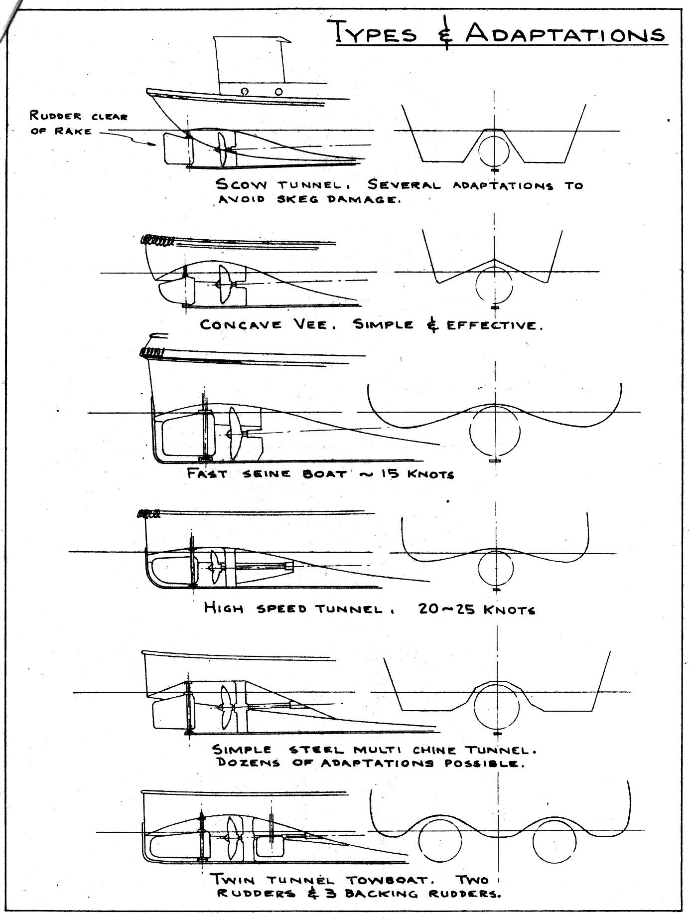
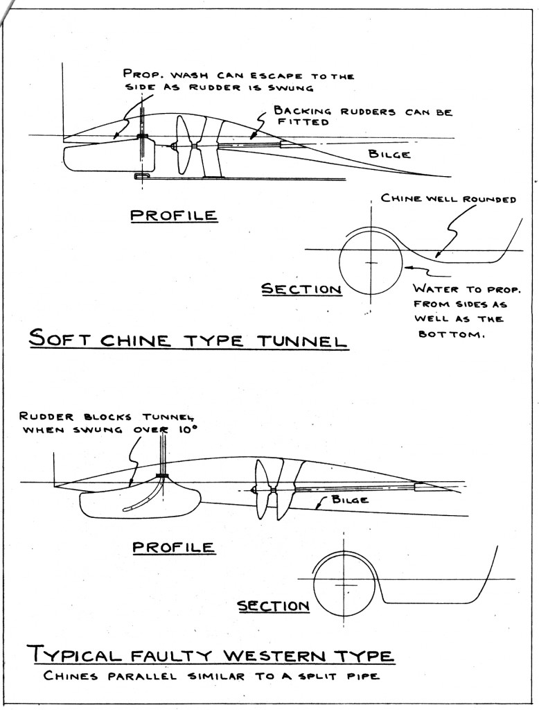
Steering is the hardest problem of all and probably can be best covered under rule number four pertaining to the chine section. A widely accepted type of western tunnel consists of a scoop out of the bottom with sharp or slightly rounded chines. With a rudder set up in such a tunnel any angle of the rudder blade simply chokes off the tunnel release and creates a lot of turbulence with very little resultant steering action. By easing the sharp chine and running the bilge up as shown in the sketch, the propeller wash has someplace to go. Also the type of stern shown allows proper space for backing rudders if those are fitted.
Another fault of the hard chine tunnel is the trouble many boats have of steering one way and not the other, since, while the wheel is turning, the part of the lower blade visible below the bottom is working in undisturbed water and kicking the stern one way while going ahead and the other while backing down. By easing the chines this trouble is minimized. Some improvement can be made by putting a vane of one-quarter inch plate about 14 or 18 inches wide directly abaft the propeller. We have done this on a couple of boats that didn’t steer and the results were worth the effort.
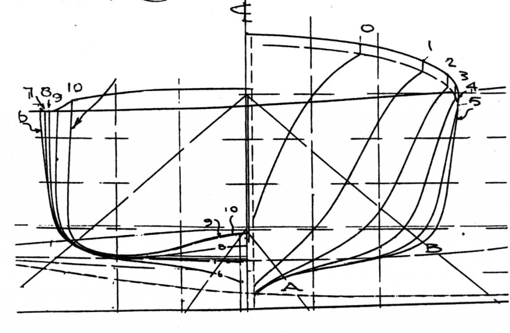
The easy merging of tunnel and bottom cannot be too greatly emphasized. The finest-handling tunnel boats that I have designed were similar to the stern shown in the photo. (missing) In this type the tunnel chines have been entirely eliminated resulting in an easy sweep from bilge to center line. The type illustrated will steer like a normal boat and will steer equally well either to port or starboard while backing down. With the hard chine type it sometimes takes a good guesser to tell which way she will steer even while going ahead. Another fact very seldom considered is that while operating in extremely shallow water the propeller must get a lot of water from the sides as well as underneath due to the proximity of the bottom. By raising the bilges aft, as shown in the the sketch, the best results may be obtained.
The profile line and distribution of volume of the tunnel is something that can stand a lot of experimental work. Possibly the prismatic or similar co-efficient of the tunnel itself would do as a basis of comparison or a standard series area curve worked out for various speed length ratios of the tunnel. It will be seen from the photo , which shows a 14-1/2 knot tunnel, that the co-efficient values would be considerably off of what they would be for a floating object of similar bulk and speed.
Development along this line would involve a very unusual proportion of prismatic co-efficient to speed length ratios. The downward hook to the profile aft should terminate just below the surface and be as flat as possible to avoid kicking the stern up through action of the propeller water on the inclined surface. Usually the shaft center line is almost horizontal, which increases the tendency. Many river boats have a tendency to root because of this reaction, so a boat of any speed must have a good lift to the forward sections.
The access hatch to the tunnel should be made of decent size and fitted with quick-acting dogs to hold it in place. A simple hatch will be appreciated when the wheel must be replaced in a hurry or if the boat has been moored bow downstream and the tunnel is filled with drift.
In practice almost any form seems to work, from a “V” to a box with the corners knocked off. Some angularity in profile doesn’t bother the efficiency measurably. Some interesting results can be obtained along this line by a study of flow patterns with a plastic tunnel model and streaks of dye. The attached sketch shows some sections easily fabricated from steel. The steel tunnels seem to work out best in a wooden boat since stern tube, rudder tube strut, and bearings can all be an integral part of the tunnel unit. The problems of alignment or tightness are simplified, damage from gravel and drift is cut down, and work can be done much easier in the welding shop than working overhead in the boat shop. The cheapest and best form of wooden tunnel seems to be similar to that in the photo and should be used whenever possible.
-
External Links
- Sorry, no links have been posted

